


Mohr-Coulomb
The Mohr–Coulomb interface model belongs to the class of elastic–perfectly plastic models. Its formulation is consistent with that of the standard Mohr-Coulomb model. Similarly, the Coulomb-type shear failure criterion is combined with a tensile cut-off criterion within a multisurface plasticity frame-work. The following figure illustrates the shear and tensile yield surfaces, including the stress return to their intersection when both yield surfaces become simultaneously active.
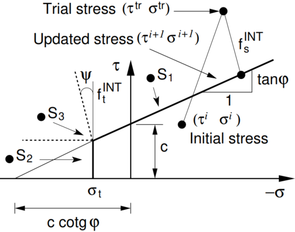 Failure surface for standard version of Mohr-Coulomb interface model
As in the standard Mohr–Coulomb model, the nonlinear response is governed by two shear strength parameters: the cohesion c and the angle of internal friction φ. The tensile strength is restricted by the condition σt < c cot φ. The dilatancy angle ψ controls the volumetric component of plastic deformation, with ψ = 0 corresponding to zero volumetric plastic strain (i.e., no dilatancy). By specifying the tensile strength, the user can limit or completely suppress tensile stresses normal to the interface. This can also be achieved using the tensile strength reduction factor TsRF, which defines the tensile strength as

The elastic response is governed by the normal and tangential stiffnesses, Kn and Ks, respectively. These parameters define the relationships between the normal stress σ and shear stress τ and the corresponding relative displacements (displacement jumps) across the interface, [[un]] = δn and [[us]] = δs. The normal stiffness Kn is generally assigned a sufficiently high value to prevent excessive interpenetration of adjacent structures under compression. In contrast, the tangential stiffness Ks may be assigned a relatively low value to improve numerical convergence, see also Linear elastic model. The stress–displacement jump relationships are plotted in the following figure.
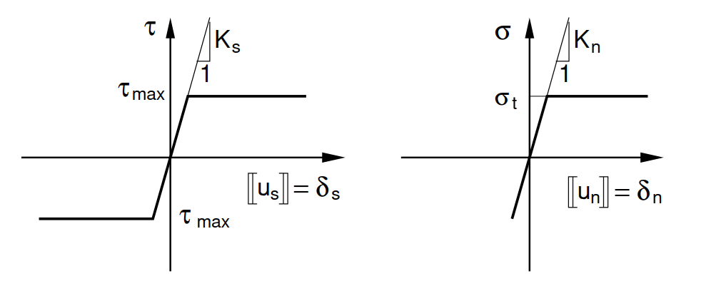 Constitutive model for interface
The material parameters defining the Mohr–Coulomb interface model are summarized in the following table. As indicated, the interface strength parameters c and φ can also be derived from the corresponding parameters of the adjacent soil, csoil and φsoil, provided that these parameters are available from the selected soil constitutive model. This applies to the Drucker-Prager, Mohr-Coulomb, and Modified Mohr-Coulomb models.
The basic model parameters are then defined as:
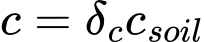

If no better information regarding the reduction of parameters is available one may use the following values. For steel structures in sandy soils, the reduction parameter equal to 2/3 is reasonable while for clays the value of 1/3 can be used. These parameters usually attain higher values when concrete structures are used. In general, the reduction parameters should be less than 1.
The dilation angle plays the same role as in the case of standard soil models. Therefore, by setting ψ = 0 the elastic behavior in the tension/compression is assumed. The plastic deformation is then limited to shear.
Symbol | Units | Description | |
Kn | [MN/m3] | Normal stiffness | |
Ks | [MN/m3] | Tangential stiffness | |
μ | [-] | Interface friction (μ = tanφ) | |
c | [kPa] | Cohesion | |
φ | [°] | Angle of internal friction | |
ψ | [°] | Angle of dilation | |
| [kPa] | Tensile strength | |
TsRF | [-] | Tensile strength reduction factor | |
δc | [-] | Cohesion reduction factor (c = δc × csoil) | |
δφ | [-] | Friction reduction factor (tanφ = δφ × tanφsoil) |

Details on numerical implementation can be found in the Theoretical manual.